Connecting Revit to a Database for GIS

You can export model component data to an ODBC (Open Database Connectivity) database. The exported data can include project parameters that have been assigned to one or more element categories in the project. For each element category, Revit exports a database table for model types and another table for model instances.

ODBC export uses metric units only. If a project uses Imperial units, Revit converts all measurements to metric units before exporting to ODBC. When you use data from the resulting database, remember that the measurements reflect metric units. Use a database function to convert the measurements back to Imperial units if necessary.

Using ODBC, Revit creates tables for the following elements:

  • Model Objects: Types and Instances
  • Levels and Rooms: Instances only
  • Key Schedules
  • Assembly Codes: A single table containing assembly code data for the entire project

ODBC export creates specific relationships between tables in the database using primary keys and reference values. See Table Relationships Within the Database.

Revit can export to the same database multiple times. When exporting to an empty database, Revit creates new tables. When you export a project to a populated database, Revit updates table information to match the project. This allows you to customize the database and re-export data as the project changes.

Attention: Do not export different projects to the same database. Use a unique database for each project.

ODBC is a general export tool that works in conjunction with many software drivers. Revit has been tested with the following ODBC drivers:

  • Microsoft® Access
    Microsoft® Excel
    • An ODBC export to Excel creates one table per worksheet.
    • You can export to an Excel file only once. Multiple exports to Excel are not supported.
  • Microsoft® SQL Server
    • The Microsoft® Text Driver is not supported by Revit.

Revit DB Link allows you to export Revit project data to a database, where you can edit the data, import it back into the project.

There are two types of databases you can use with Revit DB Link: Microsoft Access or ODBC.

The database must already exist (for non-Microsoft Access databases) and have a DSN properly set up for connecting to it. See Accessing Revit DB Link.

The Microsoft Access or SQL Server database must allow for reading, writing, and table creation.

When Revit creates database tables during ODBC export, it adds relationships to the data tables using primary keys and reference values. In relational databases, a primary key is a unique value that identifies a record (row) in a table of the database. Reference values are columns in a table that refer to other tables.

Note: Database programs (such as Microsoft® Access) can interpret the table relationships. In spreadsheet programs like Microsoft® Excel, relationships are not supported, so Revit creates simple, unrelated tables.

The primary key in each element table is the column labeled “Id”. The following table illustrates how primary keys and reference values create relationships among tables in the database.

Column (Field) of a Door Instance Table Corresponds to…
Id

This is the unique identifier for this instance of a door.

Type Id

Id column of the door Types table

Level

Id column of the Levels table

Room

Id column of the Rooms table

Key schedule

Id column of the Key Schedules table

The primary key in the Assembly Codes table is the Assembly Code column. The Assembly Code column in type tables references the Assembly Code column in the Assembly Codes table.

Revit does not create a reference for the Host Id column because the host may be a wall, floor, roof, or other such host, so there is no unique table to reference.

The relationships between tables are established only when Revit first creates the tables; if you use Revit to re-export to an existing database, no new relationships are created.

You can install the Autodesk Revit DB Link 2014 from your subscription site.

To export to an ODBC database
  1. In Revit, open the project to export.
  2. Click Export (ODBC Database).
  3. In the Select Data Source dialog, click New to create a new Data Source Name (DSN).
  4. In the Create New Data Source dialog:
    1. Select a driver, and click Next.
      1. This driver is associated with the software program you export to (for example, Microsoft® Access, dBase, or Paradox).
    2. Enter a DSN name, or navigate to the target folder and specify a file name. Click Next.
    3. A confirmation dialog displays. If any information is incorrect, click Back and correct it.

    4. Click Finish.
  5. Create the database file.
    1. Depending on the driver selected, a dialog displays, requesting information about the database file to which you’re exporting. Use the dialog to specify the database to use or to create a new one. For example:
      1. For Microsoft® Access, click Select to select an existing database, or click Create to create a new, empty database to export data to.
      2. For Microsoft® Excel, first use Excel to create a new, empty workbook with the desired name. Then on the dialog, click Select Workbook, and navigate to the new workbook.
  6. In the Select Data Source dialog, click OK.
  7. In the ODBC Setup dialog, click OK.

Note: If the export fails with an error regarding a read-only database, click Options in the ODBC Microsoft Setup dialog. Clear the Read Only check box. Then try the export again.

Do not edit data in the database columns exported by Revit. Any changes to those columns are overwritten the next time the project is exported.

However, you can add columns to the tables created by Revit. The next time the project is exported, any data in the added columns is preserved.

You can update a Revit project with changes that were made to data in an external database, or that were directly edited during import.

  • The appropriate Revit elements reflect any changes that were made to the database.
  • The import table view allows changing of data immediately before import if desired.
  • You can use Ctrl+0 to set a cell value to empty in the table view.
  • It is not possible to delete, cut or modify an entire record (using copy and paste) if the corresponding element exists in Revit.
  • Those tables that do allow creation of new types will have a new row record available. When filled out with all the required data, the ID displays a negative value which converts to a valid element ID after the import process.
  • The Custom Parameters menu allows you to create Shared Parameters for your project. Click Add and specify the Name, Group, and Type, then select the Categories it will belong to. All selected categories that have an associated database table automatically appends the new parameter field to the table. This parameter data may then be edited in the drawing or the database and updated accordingly upon import or export.

    DANGER

    Only import from the database originally exported to for a given project, or unpredictable results may occur.

Revit DB Link Workflows

Autodesk Revit DB Link provides a way to store Revit model information in a database where it can be modified and then returned to the Revit model. With Revit DB Link, you can:

  1. Create a database from data in a Revit project.
  2. Update an existing database with Revit data that has been changed.
  3. Update a Revit project with changes made in a database.

How Revit Network Version Works

There seems to be a misunderstanding of how Revit (well all Autodesk products for that matter) runs in a network environment but it’s really quite a simple process. 

Understand that CADD programs are too large and to processor intensive to run across your network as they would grind all network traffic to a halt, therefore CADD programs need to be installed on the users local computer & not on the server.  There is a very small program that sits on the server and sends a tiny file to each users computer to track license checkout status.  When determining the number of licensed seats a company needs to purchase the question is not how many users we have corporately but rather how many users need to be running the software concurrently.

This means that you may actually deploy 10 installations throughout your CADD department but only purchase 8 network licenses.  While all 10 machines are capable to run the software only 8 may be in use concurrently.

How BIM is Changing Business

One of my colleagues passed this great article along (thanks Anthony)…

As the wind whips through the top floor of an unfinished eight-story office building a block west of the White House, Steven Denbow points to metal air ducts as an example of work that wouldn’t need to be redone.

The 29-year-old senior project engineer for Balfour Beatty Plc (BBY) ran three-dimensional simulations before construction began, finding hundreds of clashes, or design elements that interfered with each other. When the software indicated water pipes would intersect the ducts, he requested changes so workers didn’t have to rebuild parts of the $29 million project.

Armed with iPads linked to the newest plans, work orders and …read more

Improve the Showcase Performance

The Showcase Help is quite umm helpful…

Combine and separate objects to improve frame rate

Large production models, which typically have hundreds of parts that are comprised of thousands of surfaces and surface patches, can significantly slow Hardware rendering performance (the frame rate) while interactively authoring or presenting a scene.

You can improve the interaction performance (even with multiple production models loaded and displayed side by side) by combining objects in the Organizer. Combining objects essentially flattens the selected object hierarchy to speed the frame rate. However, to prevent data loss (for example, material assignments), you must follow the workflow guidelines and possibly modify your workflow.

Note

Hierarchies or groups containing accent lights cannot be combined. The combine option will be grayed out and unavailable when these items are selected. Deselect or remove the accent lights from the group and then combine.

Follow these working guidelines to combine nodes successfully without losing important data:

  • Resist combining objects that go into different alternatives or behaviors. If you do combine the objects, the assignments may break, and you may need to redo the reassignments.
  • Precalculated ambient shadows may be adversely affected when you combine mixed geometry (for example, polys and NURBS). Before combining, occlusion is applied differently to different data types (for NURBS, through textures; for polys, through vertex colors); after combining, NURBS and polys textures are ignored, and all occlusion is vertex based.
  • Combining a shadow caster will result in the entire combined node being a shadow caster for that light.
  • Combining objects that may appear to have the same texture may cause the texture placement to shift or scale in unexpected ways. In this case, re-place the texture on the combined object.
  • You cannot combine a node that has already combined objects within it; the combine button and menu item is not available in this case. An alternative approach is to separate the combined node, then combine at a higher level of the hierarchy.
  • Combining should be done only if you are sure that nothing else is going to change in the geometry. If you combine and then decide to update or re-tessellate your model because of changes done in the originating application, you may encounter geometry issues.
  • When combining multiple objects with different materials, the first material found is applied to all. For example:
    • Object A is combined with Material A
    • Object B is combined with Material B

    If you combine those two objects, you get:

    • Object C With Material A
  • If you plan to animate objects, keep the objects separate.

To combine objects:

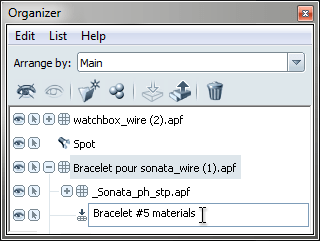
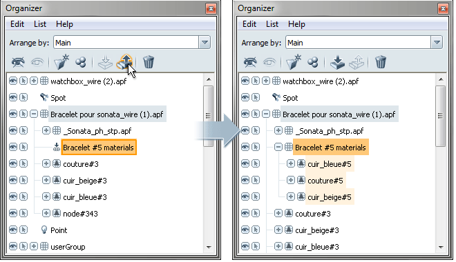
  1. In the Organizer, select the objects you want to combine, then group them. The objects are grouped into one folder.

  2. Right-click the folder with the grouped objects, and select Combine. The objects are combined and you can no longer expand the node to see its contents.

    Note

    Double-click the folder to folder to give it a more meaningful name.

You can separate combined objects to gain access to parts of the combined geometry to work with it (for example, to flip normals, to remove duplicate surface, or to split geometry to add different alternatives or behaviors).

Separating is not the same as undoing (Edit > Undo) the combination operation. Separating retains the object hierarchy but gives you access to combined objects; undoing reverts to the original object hierarchies within a scene session.

To separate objects:

  1. In the Organizer, select the combined objects you want to separate.
  2. Right-click the selected objects, and choose Separate. The objects are separated, and you can now expand the node to see its contents.

Alternative Visibility Line up in Showcase

Set up and view visibility lineups

Visibility lineups are collections of objects or their attributes that you hide or show as a unit in a scene. For example, all the parts that make up a particular design for a hubcap.

Note

A scene may have any number of model alternative lineups, but any one object can be in only one model alternative at a time.

Create a model alternative lineup

  1. Press the A key to view the Alternatives interface.
  2. Click the Create button at the top of the alternatives list.

    Note

    If you do not see this button, you may be in presentation mode. Press Tab to get back to edit mode.

  3. A list of possible types of lineups appears. Select Visibility Lineup .

    A new lineup is created to contain a new set of model alternatives.

  4. Select the objects in the scene that you want to add to the new alternative.

    Note

    If you cannot see the objects you want to add, they may already be assigned to another model alternative. You need to remove them from the other model alternative before re-assigning them (see below).

  5. In the appropriate lineup, click the Add Alternative button (called Add Next Alternative if there are other alternatives in the lineup).

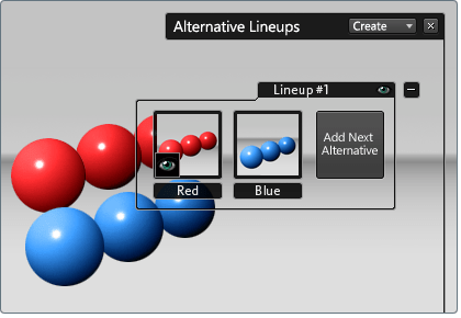
    The selected objects are added to the lineup as a new alternative. The eye icon indicates the alternative is active and its contents are visible.

  6. Double-click the name box to add a text label for easy identification of the alternative.

    Note

    When authoring alternatives, do not use special symbols like the “#” symbol within the names. If the Showcase file is ever to be used through a web interface (either remotely or locally) special symbols will make it difficult or impossible to control the alternatives using HTTP protocols.

    Continuing this example, assume you select the blue objects and click Add Next Alternative. This would create a new alternative containing the blue objects and make it the active alternative. The red balls disappear, since their alternative is no longer active.

Remove an object from an alternative

  1. Click on the alternative you want to work with to make it visible.
  2. Select the objects you want to remove from the alternative.
  3. From the alternative’s right mouse button menu, select Remove Selection From.

    The object is no longer part of the alternative. It will still be visible for the current alternative, but will also be visible for other alternatives:

Add an object to an alternative

  1. Select the objects you want to add to an existing alternative.

    Note

    If you cannot see the objects you want to add, they may already be assigned to another model alternative. You must remove them from the other alternative before re-assigning them (see above).

  2. Click the alternative you want to work with.
  3. From the alternative’s right mouse button menu, select Add Selection Into.

Delete an alternative

  1. Expand a lineup to view its alternatives. Select the alternative you want to work with.
  2. From the alternative’s right mouse button menu, select Delete Alternative.

    The alternative is deleted from the lineup. The objects in the alternative are not deleted, but they are now visible and selectable for all other alternatives.

Select all objects from a particular alternative

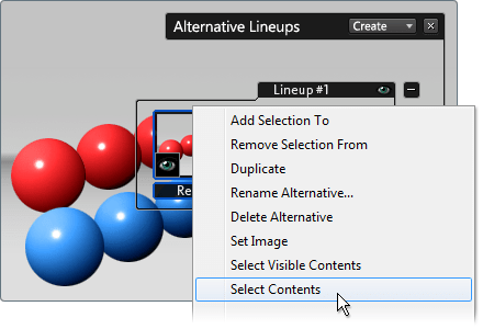
  1. From the alternative’s right mouse button menu, select Select Contents (or Select Visible Contents if you do not want to select hidden items).

  2. All objects in that alternative are now selected.

Select all objects in the entire lineup

Right-mouse-button click on the lineup name, then choose Select Entire Lineup.

Optimize REVIT Files for use in Showcase

From the Showcase Help file…

General model preparation

Be aware of these general principles when using external applications to create models that will be imported into Showcase.

For best results, models should be built in real world size in their original modeling package.

The following characteristics of imported objects may affect Showcase performance:

  • Number of objects
  • Number of polygons
  • Amount of materials
  • Size of material texture maps

Once models are imported, use the following Showcase features judiciously to avoid performance impacts:

  • Shadows
  • Screen-Space Ambient Occlusion (SSAO)
  • Animations

Prepare Revit models

Follow the guidelines described here for best interoperability between Revit and Showcase.

Revit Version

For best results, save your Revit file with Revit version 2014 before importing into Showcase.

Cameras

You can only export one camera at a time. The camera in the active 3D view at the time of export is the camera that is saved to the FBX file.

Geometry

To exclude certain geometry from the export, hide it using the “Hide in view” feature or the Visibility/Graphic Overrides window. Using Temporary Hide/Isolate does not exclude geometry from the export.

Unsupported items

The following Revit features and elements are not supported in Showcase:

  • 2D line work
  • Lights
  • Design options are not fully supported
  • Phases are not fully supported
  • Entourage (RPC) is not fully supported

Number of objects

Should you experience performance issues in Showcase while working with your Revit geometry, consider combining geometry in the Showcase Organizer to reduce the number of objects. It is best to do this once you are sure you will not need to re-import the data from Revit. Updating and re-importing data that has already been combined in Showcase will likely result in many visual issues.

Another alternative is to break the Revit model into multiple parts and import them separately. For example, export a building view that has everything hidden except the first floor. Then export a view that has everything hidden except the second floor, and so on. Then you can optimize each file in Showcase before importing the next.